LED Behavior Matrix
This page explains the behavior and purpose of each LED indicator on the OV80i camera, based on color and function.
Use this as a quick visual reference during setup, inspection, and troubleshooting.
LED Locations & Meanings
The OV80i includes 4 LED indicators on the top panel of the device, each with a distinct purpose:
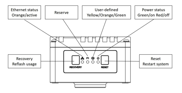
| LED Label | Color | Function |
|---|---|---|
| Ethernet Status | 🟠 Orange (Active) | Indicates network link or activity |
| Reserve | (Off) | Reserved for future use |
| User-defined | 🟡/🟠/🟢 Yellow, Orange, Green | Reserved for software-defined behaviors |
| Power Status | 🟢 Green (On) / 🔴 Red (Fault) | Indicates system power and health status |
Button Functions
| Button | Function | Notes |
|---|---|---|
| Recovery | Reflash usage | Only use if instructed by support |
| Reset | Restart system | Safe reboot |
LED Quick Reference Table
| LED | State | What It Means |
|---|---|---|
| Ethernet (🟠) | Solid or blinking | Network link present and active |
| Power (🟢/🔴) | Green = On | System is powered and operational |
| Red = Fault | Power fault detected (check power input) |
Field Usage Notes
- Ethernet LED not lit? → Check cable seating, switch status, or static IP conflict
- Power LED is Red? → Confirm 19-24 VDC input and M12 connector seating
- User-defined LED has an unexpected color? → Check the logic in your Node-RED flow.